Service Details
Selecting Cylinder Bore Size
When selecting a cylinder bore size for your application, first determine the maximum push or pull force required. Next, add at least 10% to the push/pull force or the working pressure to compensate for pressure drop in the line and friction in the cylinder. This 10% figure is adequate for normal applications. Finally, knowing the working pressure available, select your cylinder bore size.
Selecting Cylinder Rod Diameter
Standard Rods - Standard rods can usually be selected when a cylinder is used for a pull or tension application. In some applications where long stroke cylinders are used for pull or tension, oversize rods may be required to eliminate rod sag.
Oversize Rods - Oversize rods are often required when a cylinder is used in a thrust or push application. In these applications, the designer must treat the piston rod as a column in compression and specify a rod large enough to prevent rod buckling.
Rod Diameter Selection
To determine the correct rod for your application, follow the steps listed below: (it is a good idea to print these out so you don't have to scroll as much)
- Determine the load or maximum thrust required.
- Classify your application as one of the various mounting types.
- Determine stop tube length--see stop tube instructions.
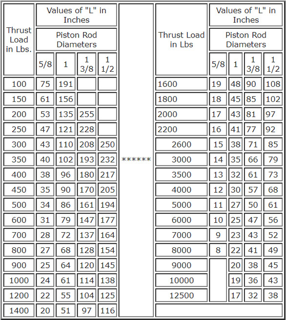
- Determine the value of "L" for your application with the rod fully extended. (See dimensional chart below)
- By referring to chart, select a thrust figure from the left-hand column, equal to or greater than the thrust of your application.
- Scan to the right of the thrust figure selected until an "L" value is equal to or greater than the "L" value determined above.
- Follow the "L" value column to the top of the chart to find the recommended rod diameter.
- In some cases, the recommended rod diameter may be larger than is available in the bore size selected. In this case, a larger bore size should be selected.
Stop Tubes
A stop tube is a spacer placed between the piston and the rod end head to reduce bearing loads. The reduction in bearing load is done by increasing the distance between bearing surfaces.
Stop tubes are recommended for mounting types I and II any time the "L" dimension of that application exceeds 40".
Stop tubes are normally not required with mounting types III and IV but the designer should use his own discretion to keep bearing loads to a minimum. Stop tubes should be specified at a rate of 1" for every 10", or fraction thereof, over an "L" dimension of 40".
Adjust "L" dimension by adding stop tube length when using "L" to determine rod diameter.
Note: Increasing rod diameter to reduce bearing load is not recommended. Stop tubes are more effective and generally more economical.